Setting a Precedent: The Electra Fly

Precedent-Electra-Fly (13) Simple and elegant lines

Gliders aren’t really my forte.  Aside from no engine (I’m a petrol-head 😉), and as much as I like the charm of circling with the buzzards and catching that thermal, I just don’t have the patience.  Furthermore, and possibly as I also fly rotary wing, I cannot help but correct every little buffet and twitch made in flight. On a glider this is a no-no. A glider barely floats above stalling speed and every time you move the control surfaces you snap away at what little airspeed the model has and quickly loose altitude. Despite all this I keep getting the urge to try again and then this popped up on eBay.

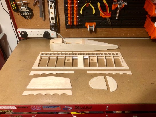
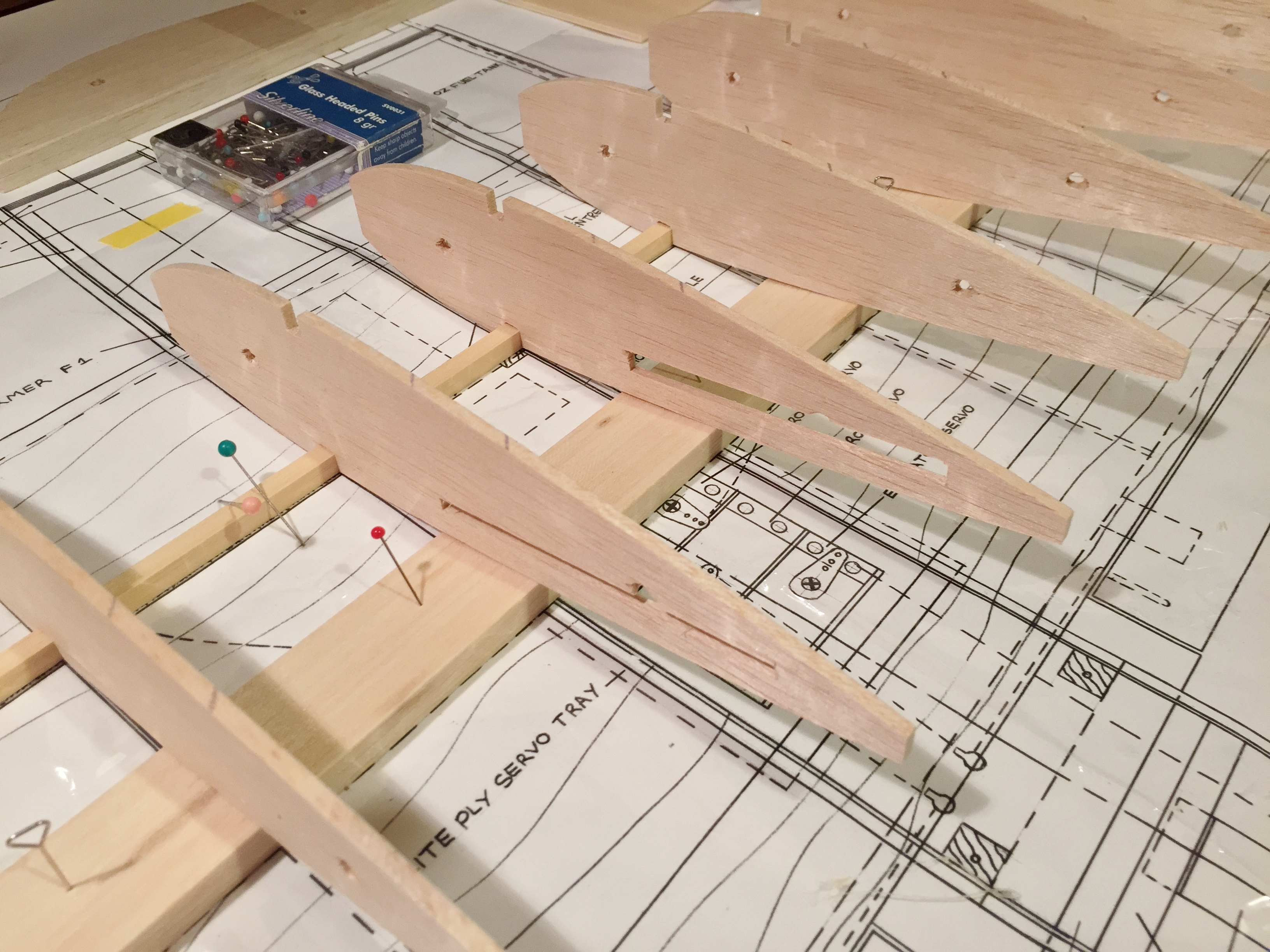
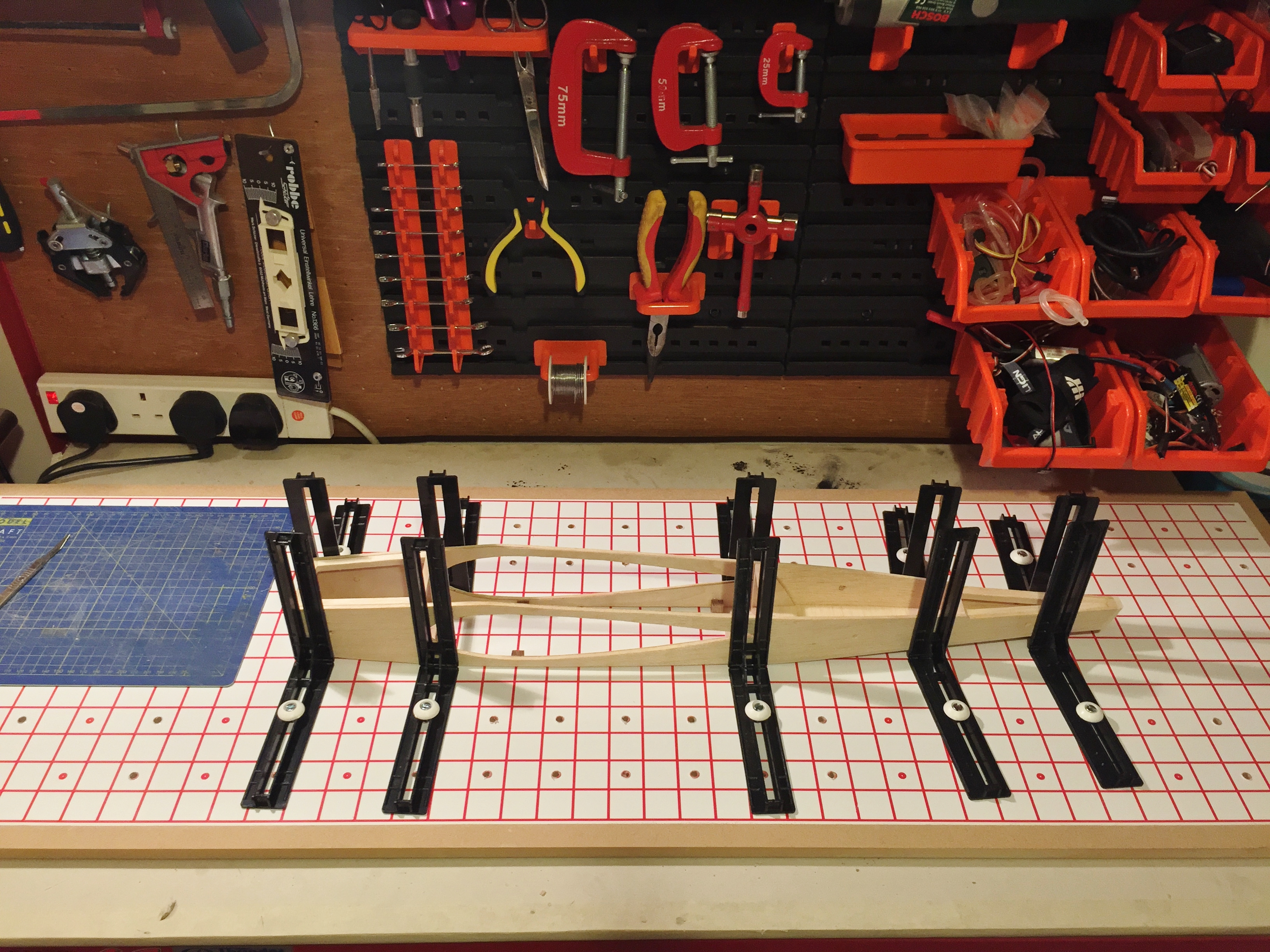
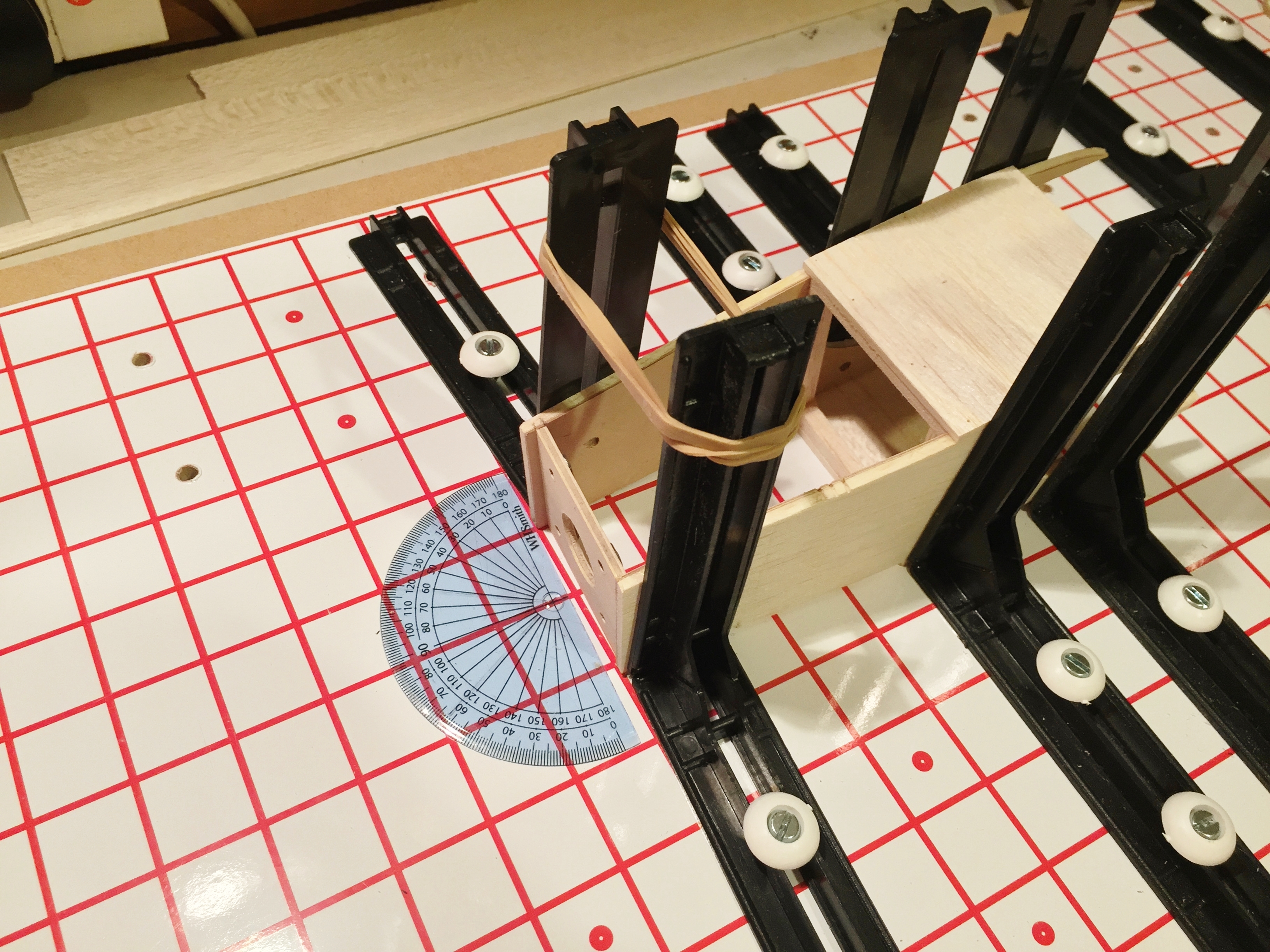
The Precedent Electra Fly was designed in 1991 and offered an ideal introduction to both model flying and, still novel as it was at the time, electric flight.  Construction was typical Precedent (now marketed under Slec) with a lite-ply fuselage that semi-assembled quickly in your hands.  The idea was to allow absolute beginners to assemble a straight model without needing a fuselage jig.  My trusty old jig was used as an insurance, but I can confirm that all the formers lined up perfectly.

Precedent-Electra-Fly (1) 
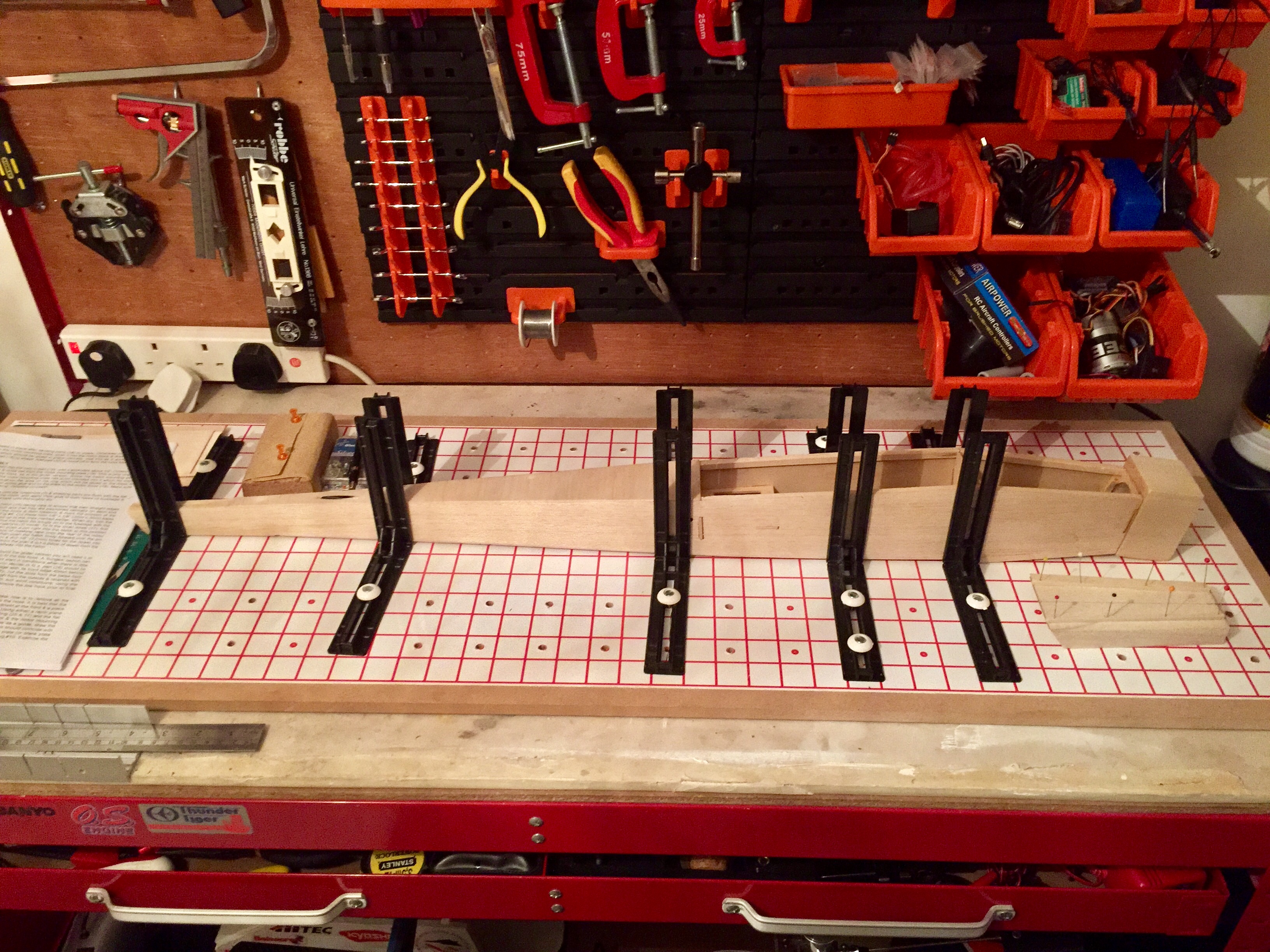
Assembling the fuselage in my trusty building jig.
Precedent-Electra-Fly (4) 
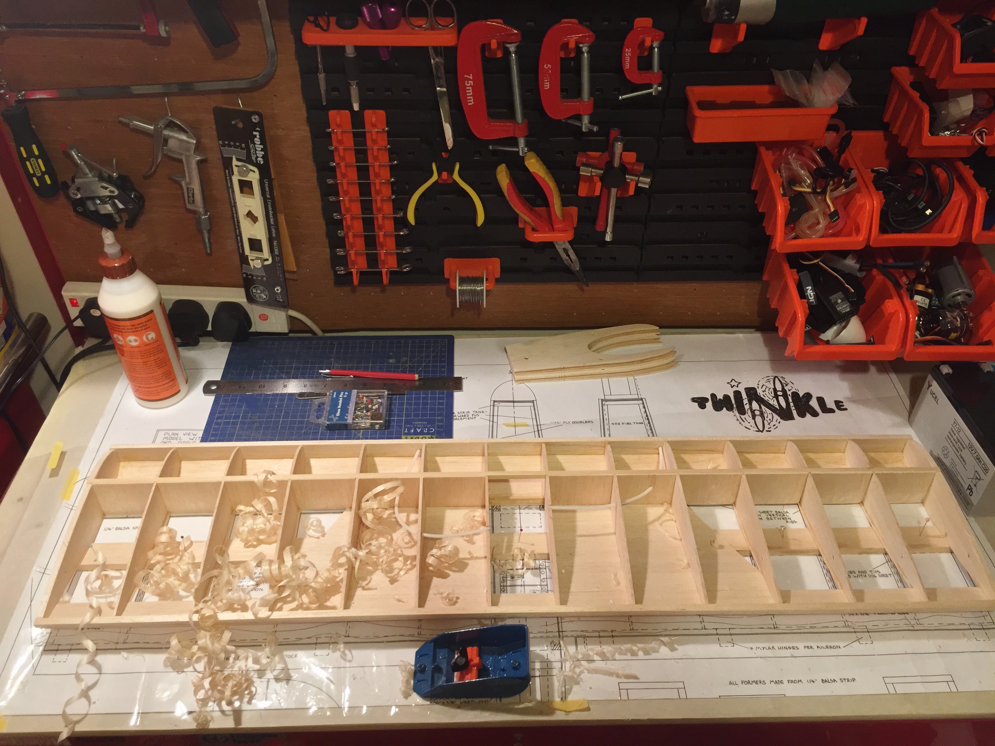
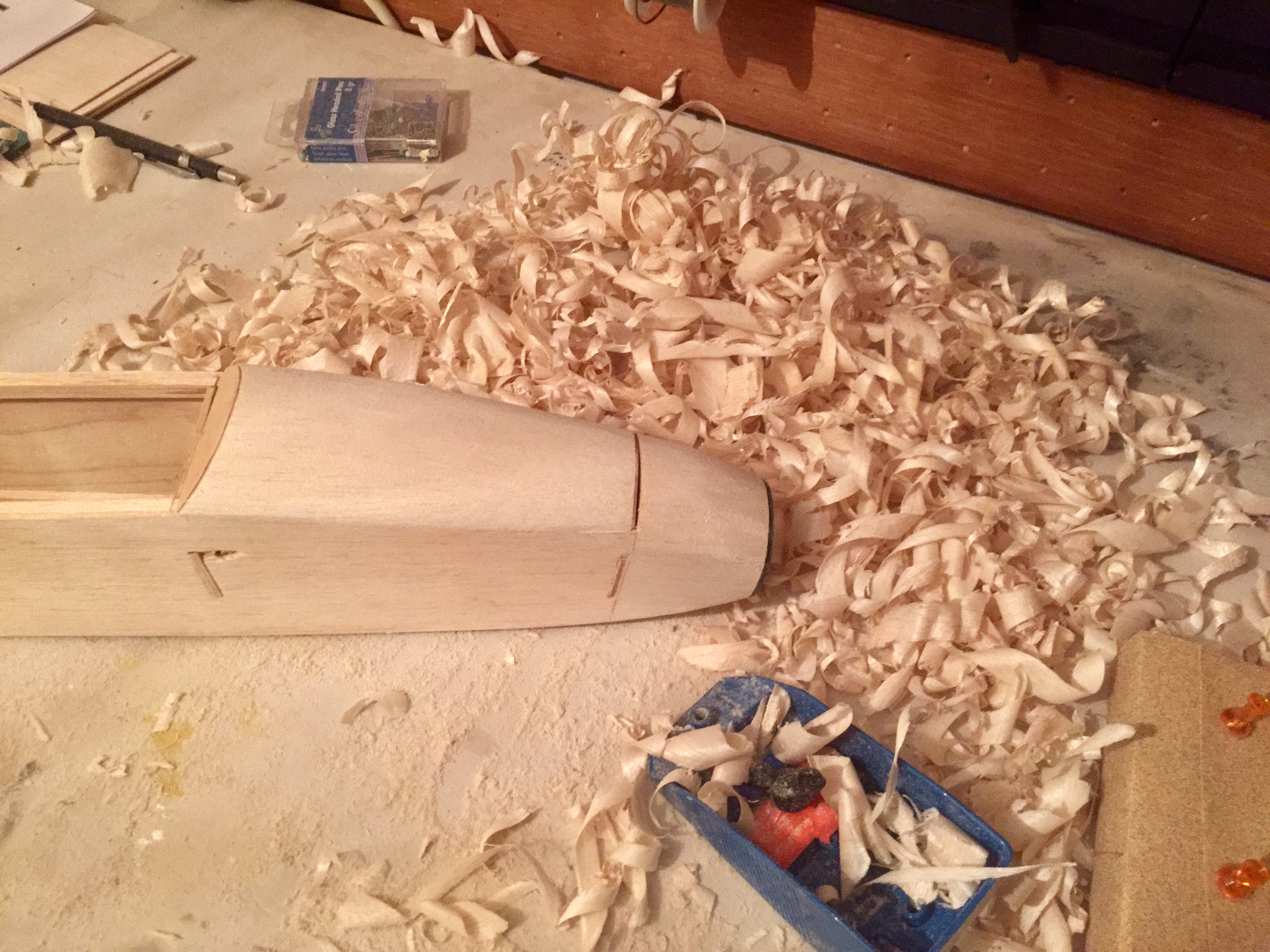
The nose sections consist of solid balsa blocks that need to be carved to shape – been a whole since I’ve used a wood plainer on a kit. Soon had a nice pile of wood shavings built up complete with a sense of satisfaction at a job well done 😊
Precedent-Electra-Fly (5) 
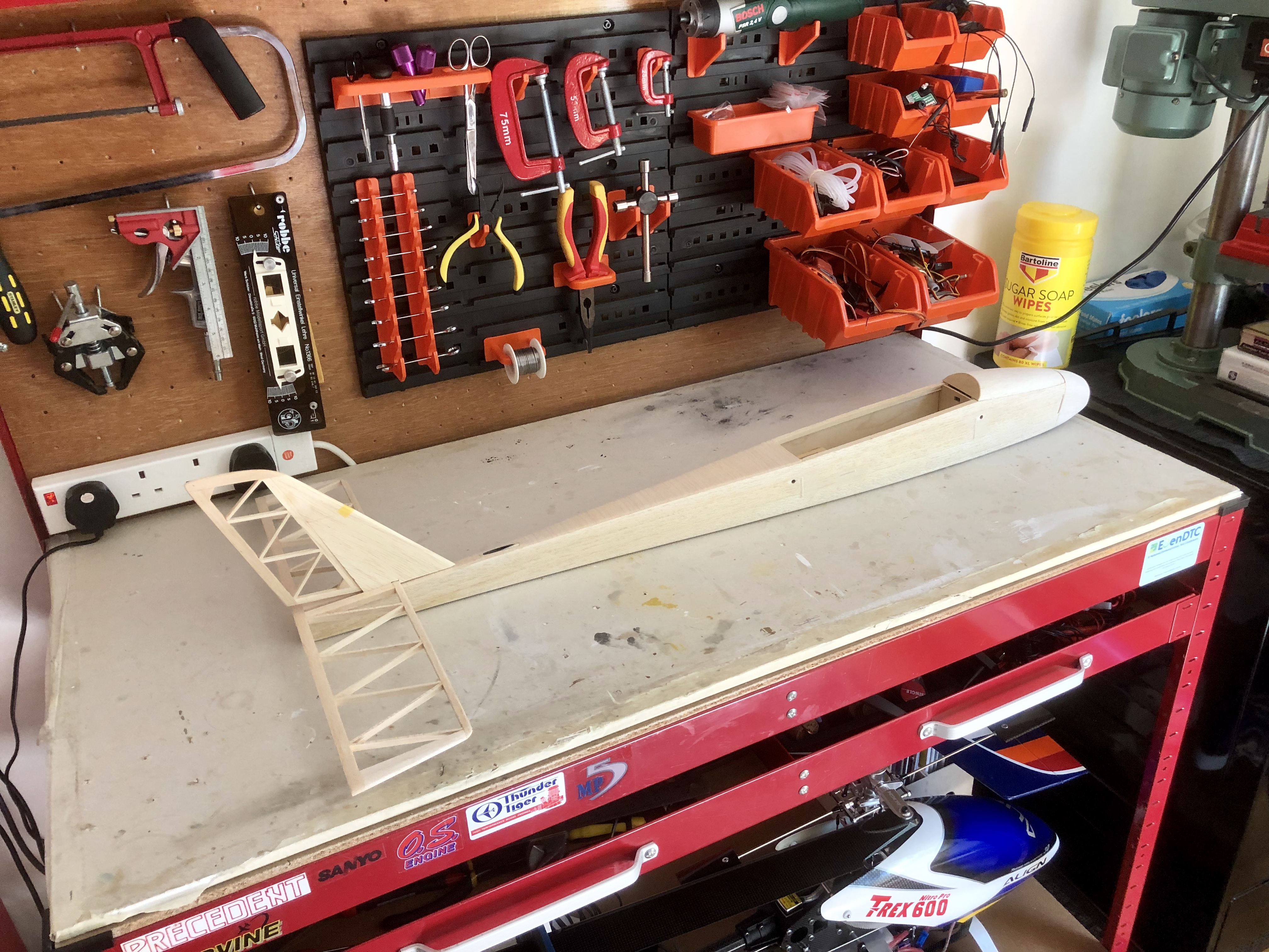
Sanded smooth and ready for covering.

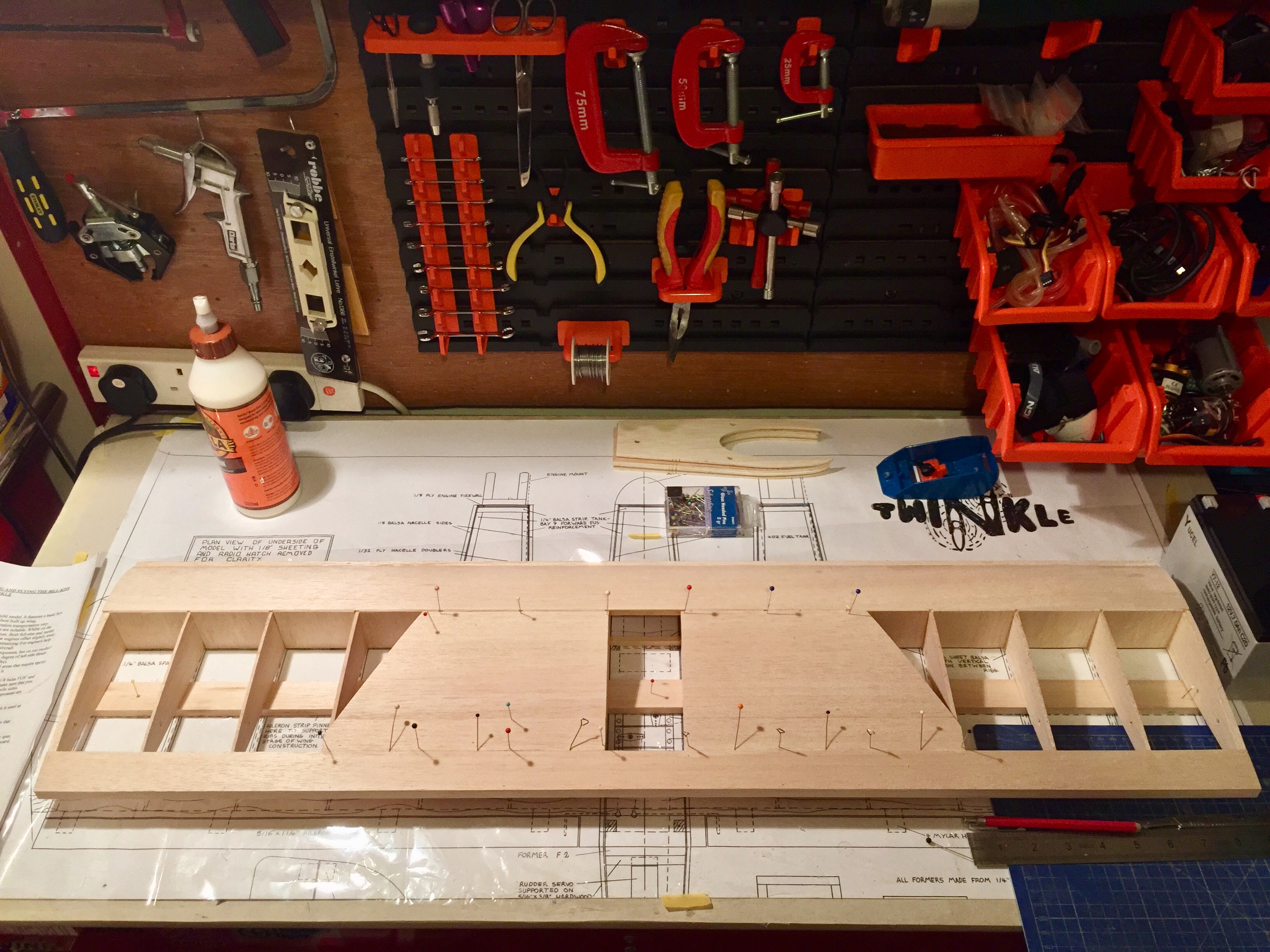
The wings were another matter.  After several decades in a box the spars had warped considerably and took a lot of painstaking steaming (and scalded fingers) above the kettle to straighten things out again.

Precedent-Electra-Fly (7) 
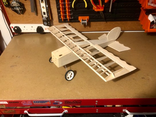
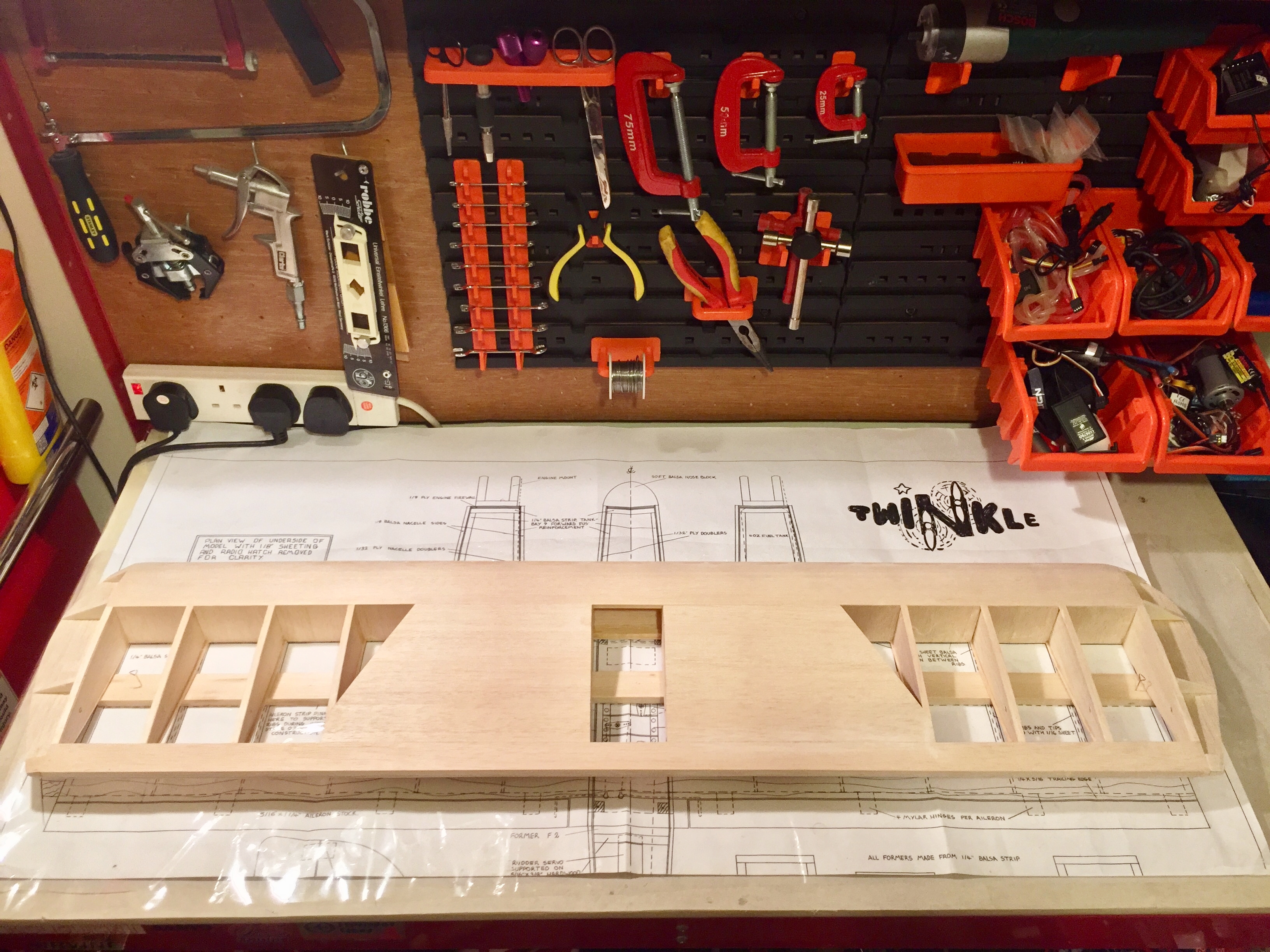
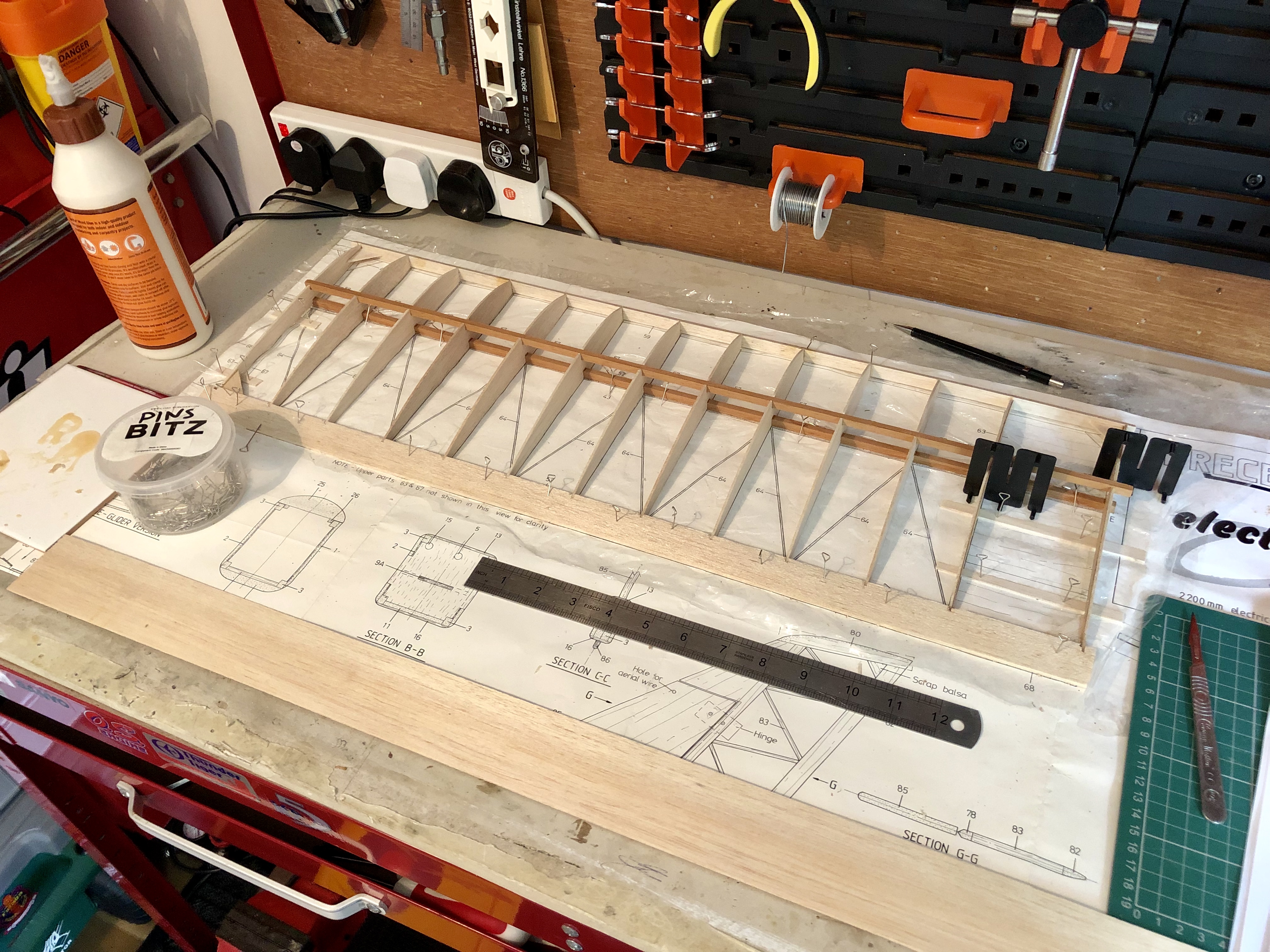
Once the spars were strighted out, the wings went togther smoothly. There is a lot of wing area to build and things are kept interesting with those novel diagonal rear ribs.
Precedent-Electra-Fly (9) 
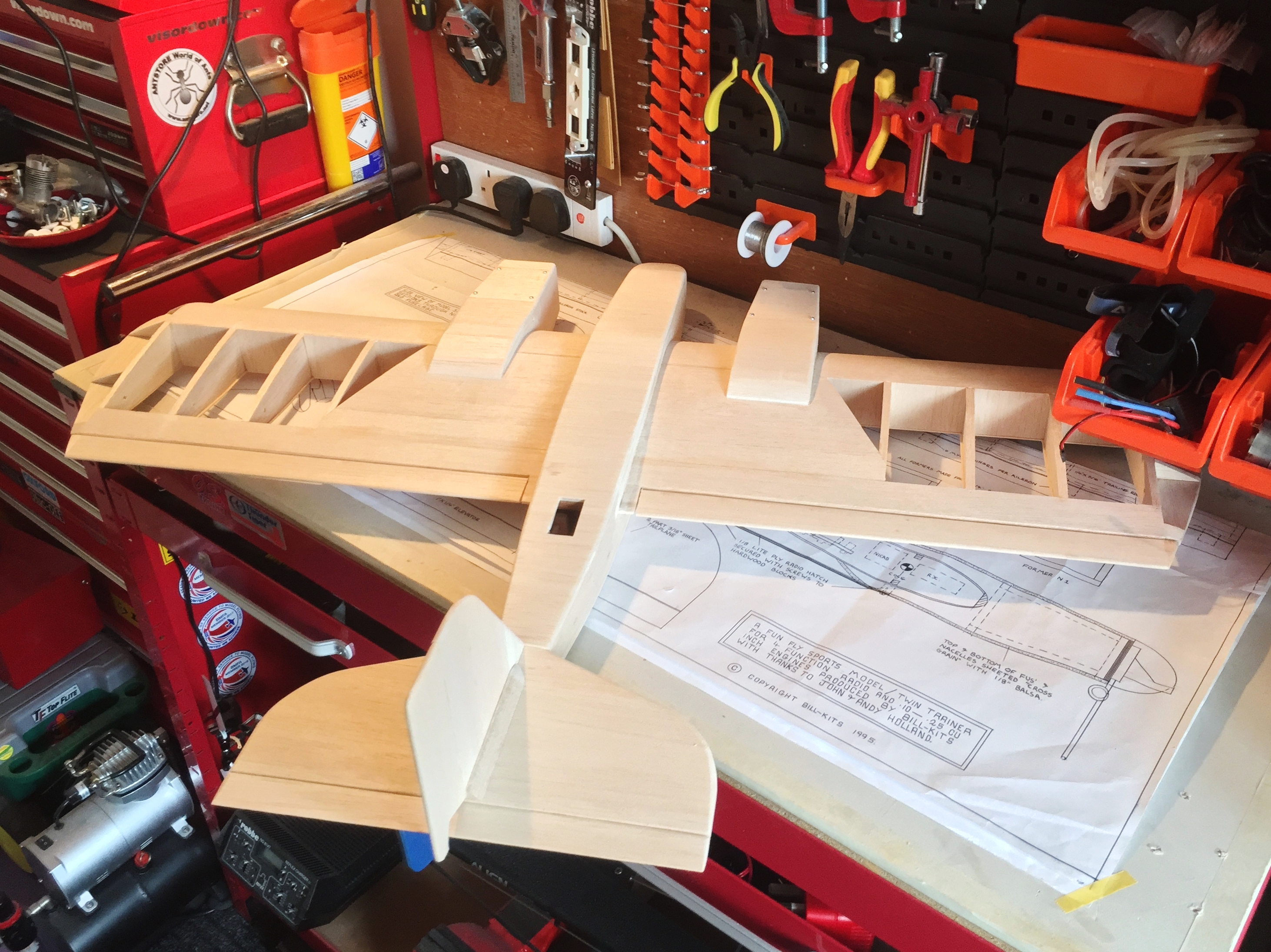
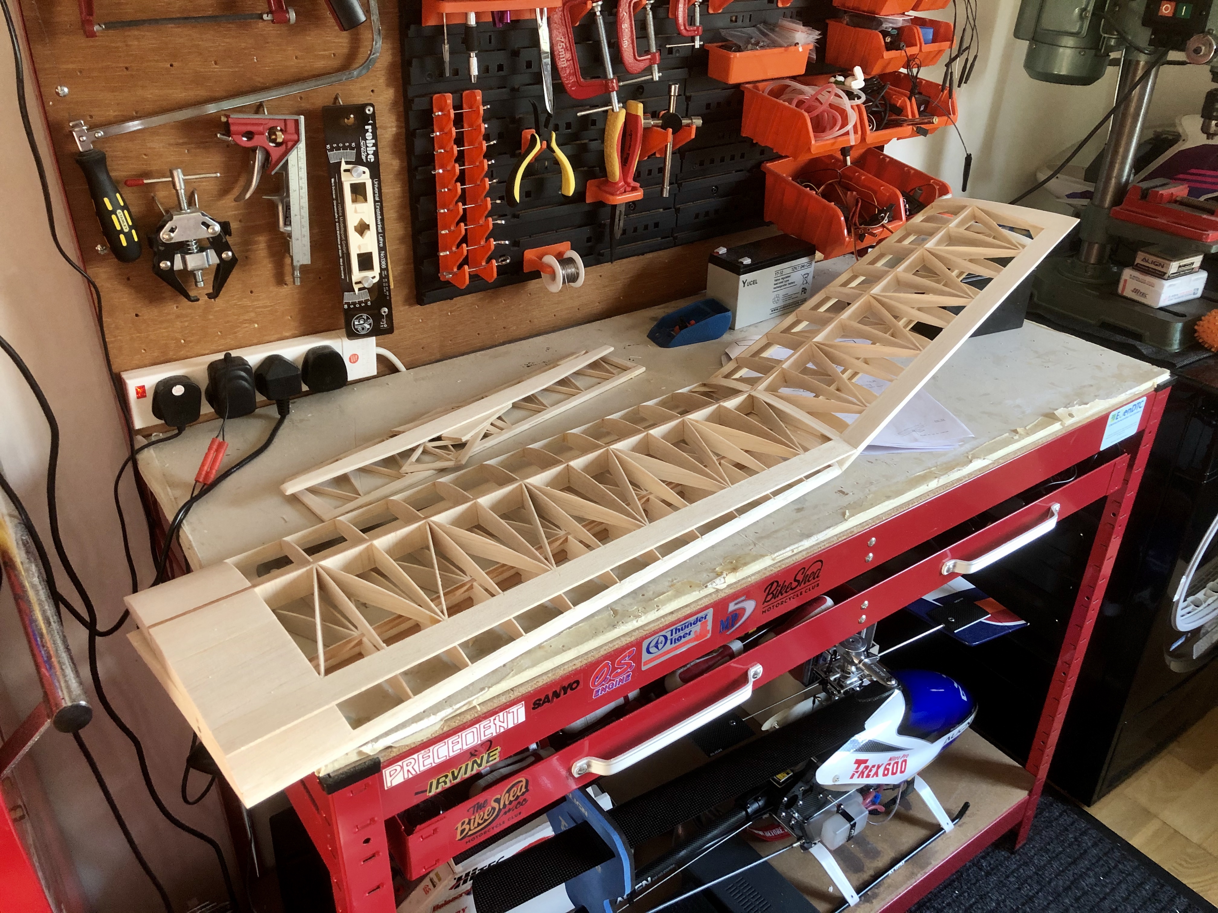
Finished wings. I understand later kits came with a sheeted forward leading edge to stiffen the inboard panels as motors become ever more powerful. Mine didn’t include this upgrade so it must have been an earlier kit. I will just have to keep flights sedate to not overstress the structure.

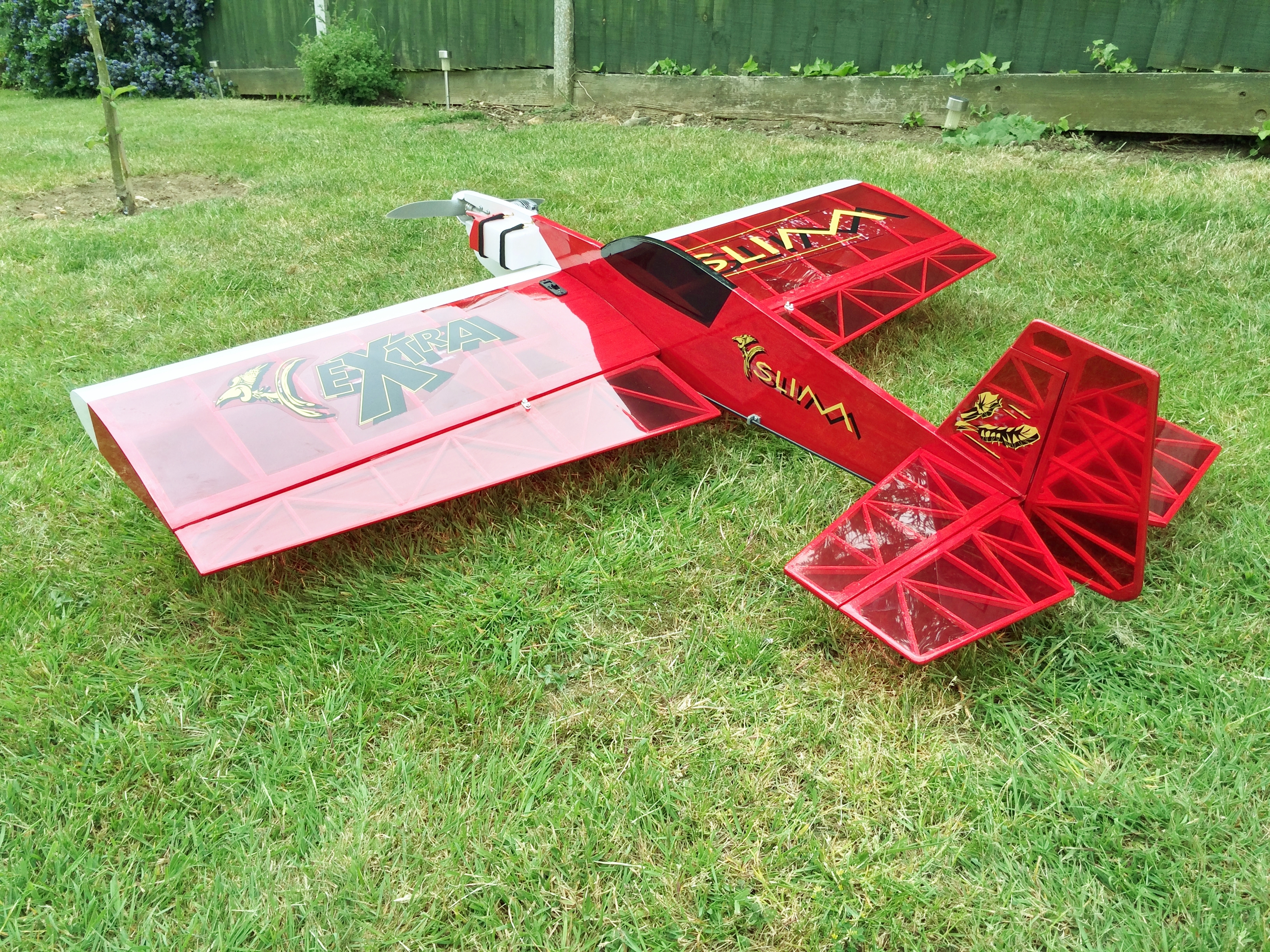
Fully assembled this is a largish model with a wingspan of 2.2m.  I opted to reduce the dihedral from the outset to that recommended for those who can already fly.  One modification I did make was to glue the metal brace rod into one wing to eliminate any chance of it rotating in flight and altering the dihedral.  Something that I uncovered after a search of old forums be an issue with this model due to the way the wing can, if going too fast, ride up at the front over the canopy seating.

Precedent-Electra-Fly (10) 
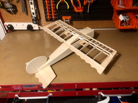
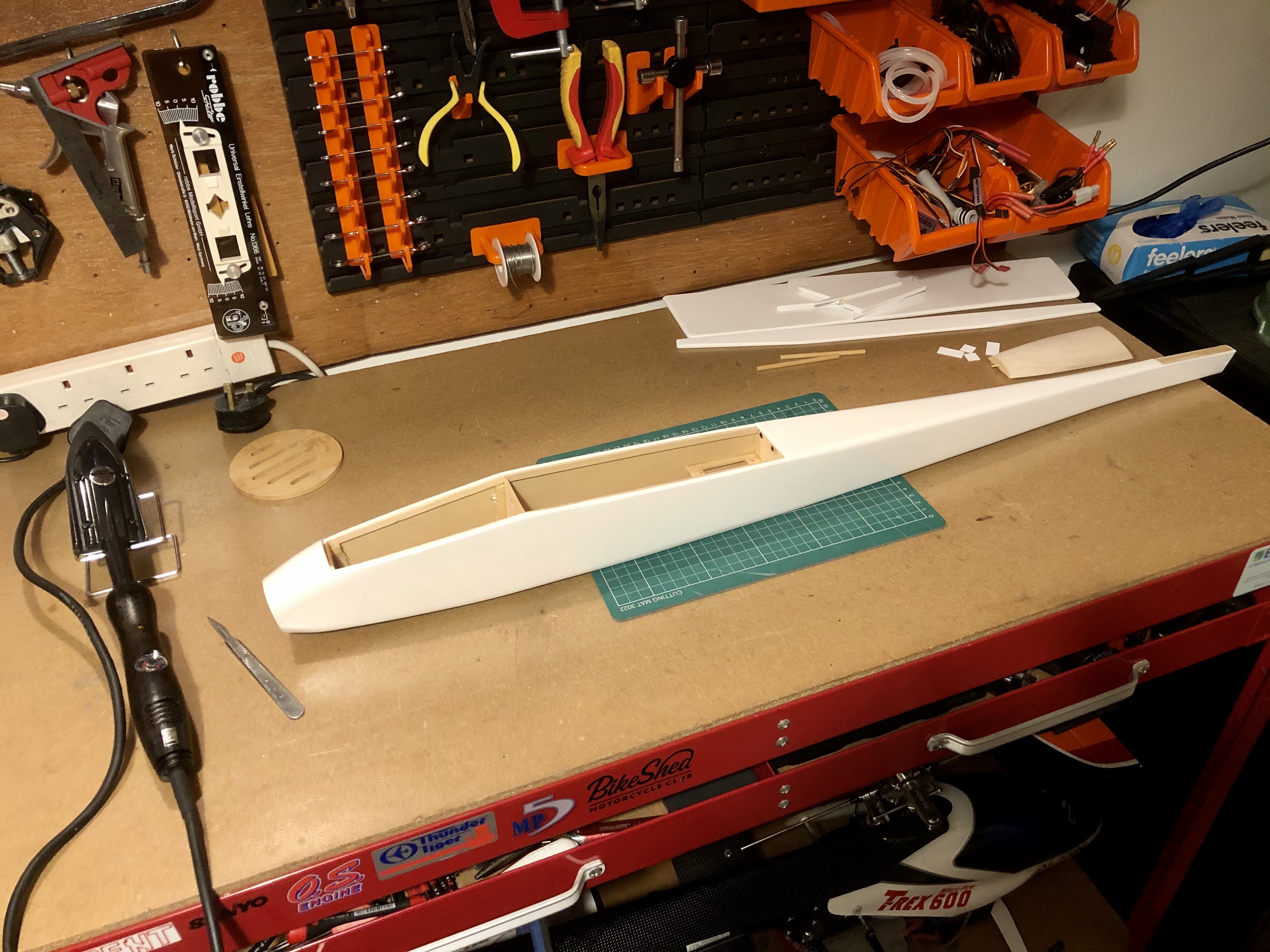
Fuselage and tail surfaces covered.
Precedent-Electra-Fly (11) 
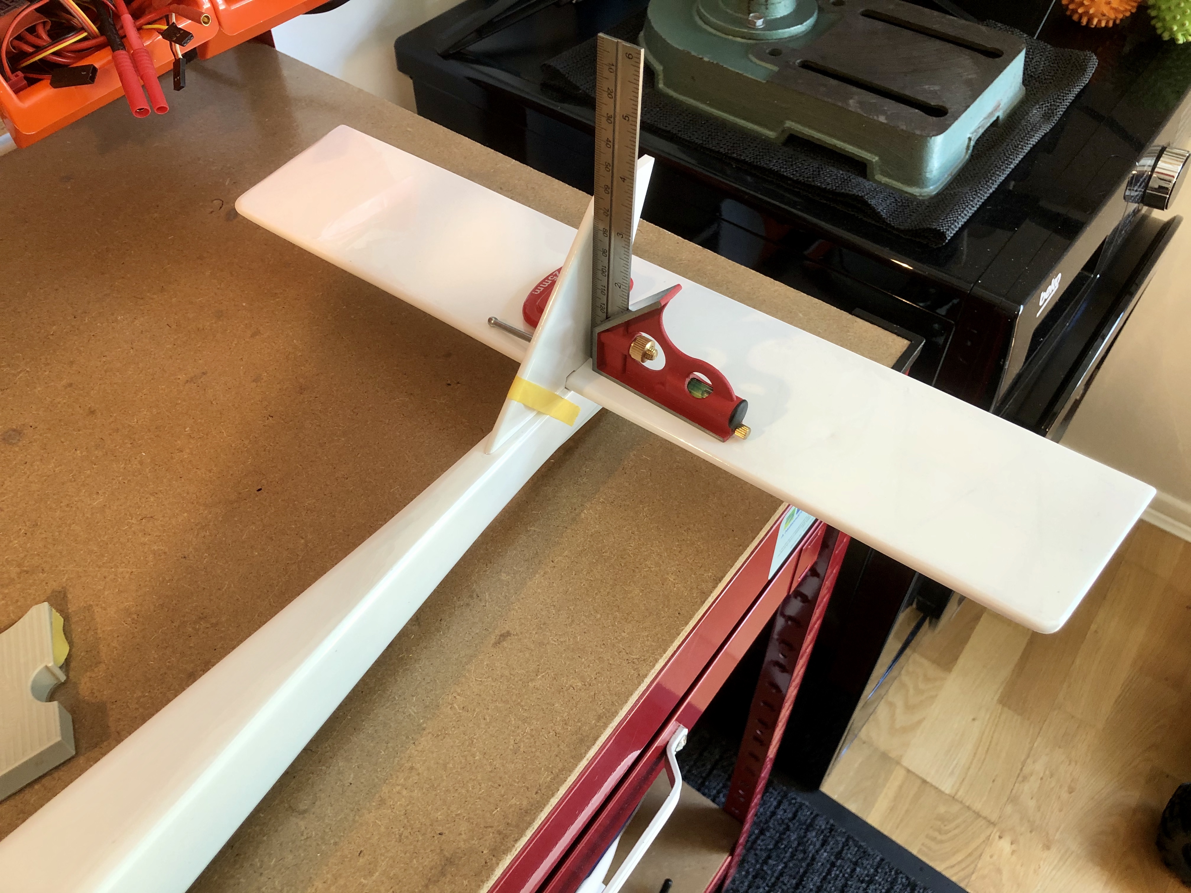
Keeping things square when gluing on the tail.
Precedent-Electra-Fly (14) 
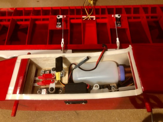
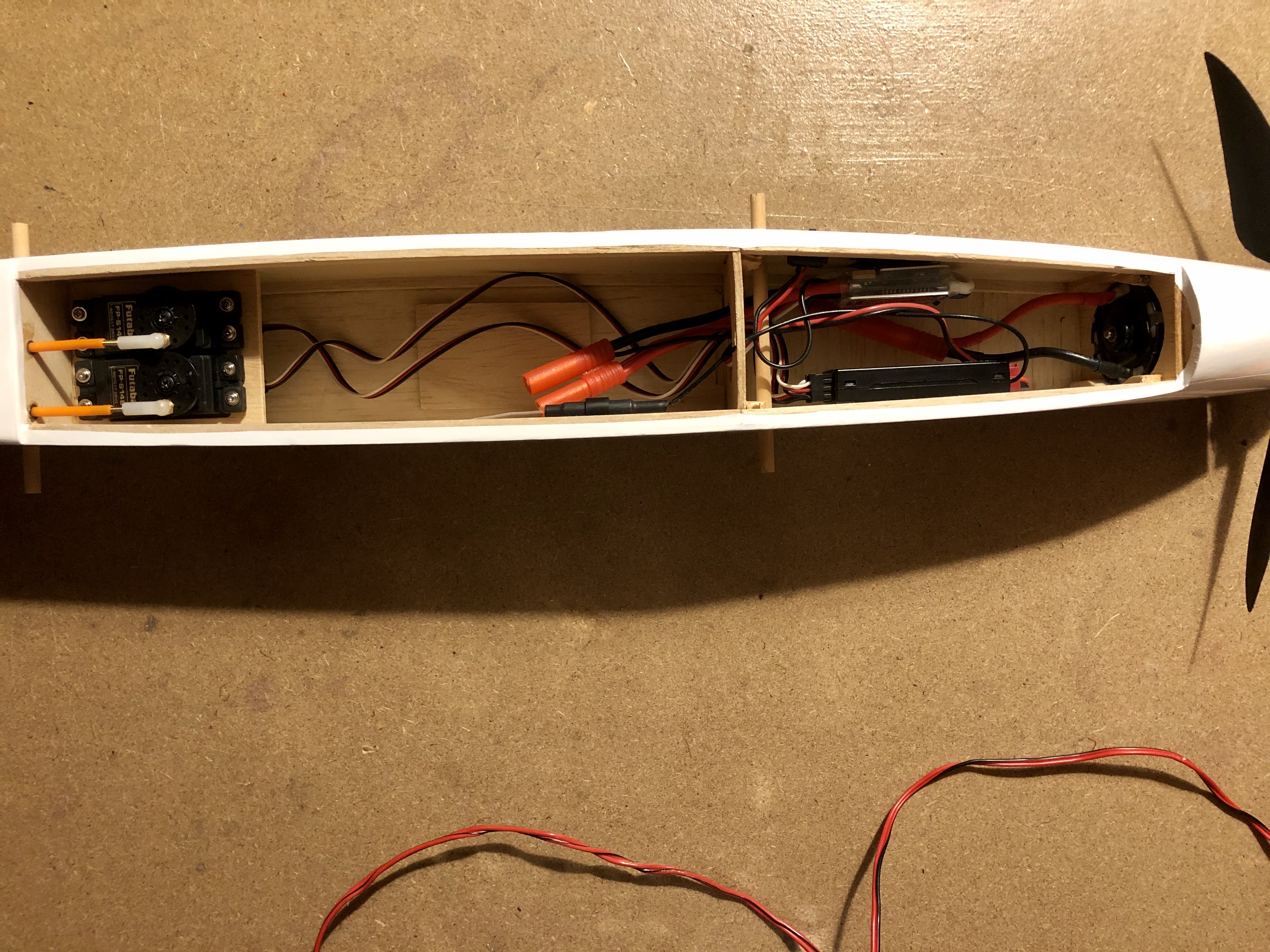
Plenty of room. When first marketed, the Electra Fly’s front compartment would have been filled with a separate receiver battery, and the (then much larger) receiver would have been squeezed in on top of the flight pack in the aft section. There was also an option to use the elevator servo to actuate a rudimentary motor control switch. Full down elevator to turned things off and full up to switch back the motor back on. I can only image the terror this must have induced!
Precedent-Electra-Fly (12) 
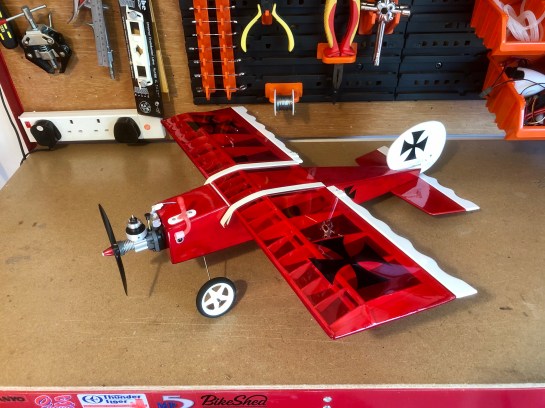
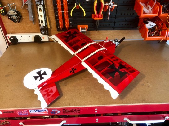
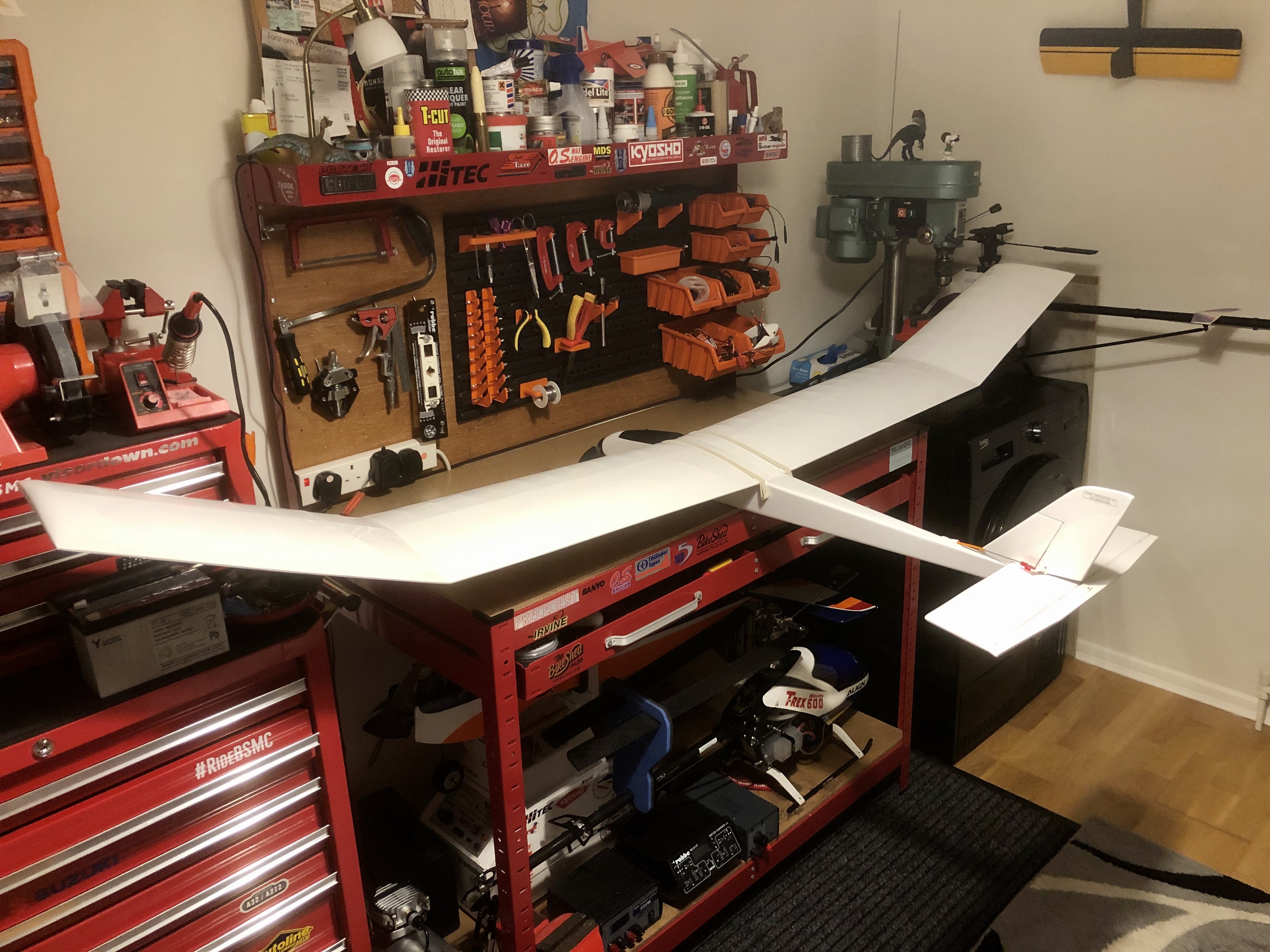
Fully rigged and she only just fits on my bench 😬.

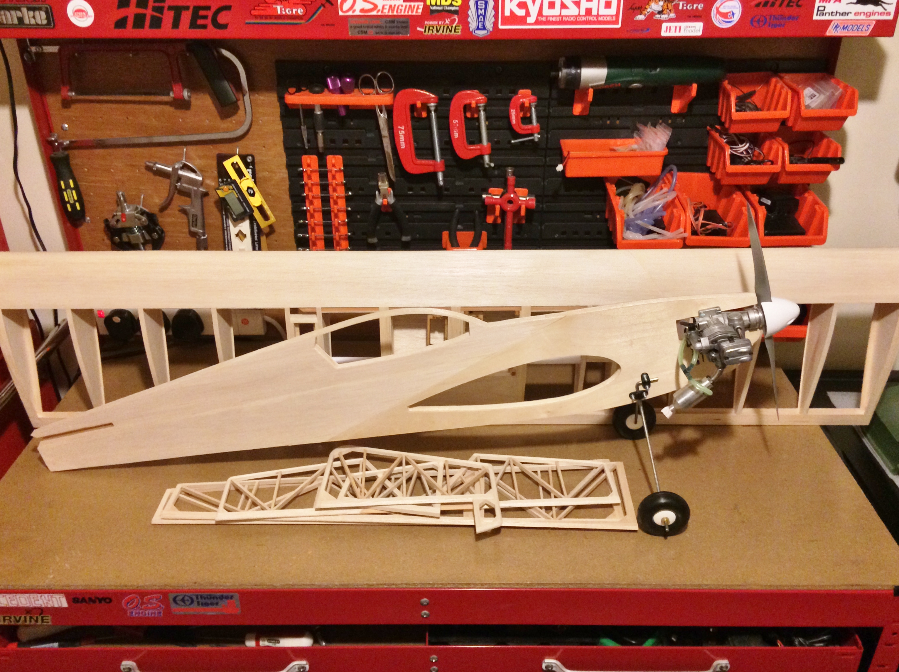
The standard 600 takes it aloft adequately but converting to brushless would be straightforward enough as a 3660 inrunner is the same dimension as a brushed 600 can motor.  The switch would be more for power efficiency than for any increase in power. This model was designed when electric flight was still novel and folding the wings would be a real possibility if things got too fast.  There is no reason why I couldn’t keep a brushless dialled back and just reap the increase in battery duration.  Cooling might be an issue with that fully enclosed motor block; especially as all the 3660 brushless motors I can find online seem to be fully sealed units aimed at cars and boats; brushless motors don’t work when wet.

A Savage Lockdown

200516_HPI_Savage_21 (2)

I don’t care – do you.

Servicing a HPI Savage 21 Truck

Lockdown hasn’t been easy so some good friends of mine suggested I needed a distraction and why don’t I look at their old RC truck and see if I can get it going again? This turned out to be a very tired but all original HPI Savage 21 which had last been used over 16 years ago in Canada!

On my work bench to take stock – well the axles turned so that was good… The engine however didn’t as it was seized solid and would need a strip down. The rest; well it was caked in rock hard mud and castor oil (yuk!).

200516_HPI_Savage_21 (2)

“Muck and filth everywhere, Mr Warwick…. It’s like a pigsty!” (Kenneth More as Group Captain Barker, Station Commander RAF Duxford. Battle of Britain, 1969).

First thing to do was remove the engine followed by a good scrub to remove the dirt, strip down and then clean. Inside, aside from corroded bearings, the rest was fine once the castor varnish was removed. Reassembly was straightforward enough aside from those fiddly clutch springs; yes it took me over an hour to find one after it pinged off into the corner of my workshop!

200516_HPI_Savage_21 (4)

One very dirty engine sitting next to an even grubbier chassis.

200516_HPI_Savage_21 (8)

Engine components cleaned and ready for reassembly.

200516_HPI_Savage_21 (12)

Gleaming. There is something special about a rebuilt engine; it’s full of latent potential.

The wheels on a truck like this need to look the part. Unfortunately, the chrome paint had long since been eaten away by oil fuel residue. Chrome is not exactly a cheap paint and would hardly be worth the effort to repaint over buying new wheels. As I already had black in stock, we agreed to change the colour; much more 2020 anyway. When putting the tyres back on and before regluing I first treated the rubber. That way the thin cyanoacrylate glue won’t stick to the outside of the rims or tyres making for a much neater job.

200516_HPI_Savage_21 (16)

As to the mechanics, there was nothing else for it but to place in the bathtub, spray liberally with oil and leave to soak overnight. All the bearings seemed to check out and aside from reoiling the suspension all was good (and certainly cleaner!). With the lower differential covers removed I added some fresh grease on the gears.

200516_HPI_Savage_21 (13)

A bit of soldering was required to replace the lead on the throttle servo.

200516_HPI_Savage_21 (14)

Back in one piece again. I’ve added an exhaust extension which should help to deflect the gunk away from the rear wheel and suspension.

200516_HPI_Savage_21 (14)

Left side

200516_HPI_Savage_21 (18)

Ready to rumble!

Lock Down Distractions: P.O. Snoopy vs an Ugly Stik 049

200425-Ugly-Stick-049 (9)

Pilot Officer Snoopy showing the world how to look groomed even when in Coronavirus lock-down.

Fighter ace pilot officer Snoopy needs a new plane to call his own! For such a figure stooped in doggy history nothing short of a WW1-esk war bird will do.  Now my little snoopy figurine is a little on the short side so it would have to be something small. I’ve always harboured a soft spot for the diminutive Cox engines so putting two and two together and a 1/2a sized model seemed the way to go.

The Ugly Stik design is almost as old as radio-controlled model planes themselves and range in size from .020 thought to some true monsters. My kit was advertised on eBay and came jig assembled leaving a blank canvas (in the instructions!) for the modeller to decide on the engine and radio installation.

200425-Ugly-Stick-049 (1)

Components completed, sanded and ready for covering.

200425-Ugly-Stick-049 (3)

The scale wheels were the only accessories included in the kit but are a nice touch.

200425-Ugly-Stick-049 (2)

Dry assembly.

I made a few modifications by opting to fit a throttled Cox Cruiser .049 and added a rudder. I used wing mounted servos with paper tubes to carry the leads. Hitec HS65MG throughout on the flight controls. There is no room in the nose (being designed no doubt for cox engines with integral tanks) as the vertical undercariage block and wing dowel are in exactly the wrong places. Instead I squeezed a 2oz tank under the CG where it won’t impact flight performance as it empties. To offset the long fuel lines, I used an old free-flight trick of routing the tank breather in line with the prop-wash to gain some semblance of tank pressurisation.  Cox engines are upright creatures at heart but this should allow for longer vertical climbouts, slow rolls etc.

200425-Ugly-Stick-049 (6)

Small can be beautiful. Transparent red Solarfilm really makes the model stand out and imparts a lustrous shine on the solid wood fuselage. The black Maltese crosses were cut from Solartrim.

200425-Ugly-Stick-049 (7)

Final weight came to 450g. I’ve not exactly made any efforts to save weight so not to bad considering the metal geared servos, 2oz tank, 900mah battery pack and standard receiver. I fly from grass so prefer ruggedness over a slower stall.

200425-Ugly-Stick-049 (8)

All neatly packed in.  I ran snakes to the rear control surfaces. Note that the servos are soft mounted using a piece of silicone fuel tubing.  Micro servos do not routinely come with grommits but never be tempted to hard mount micro servos in an IC model. In the background you can see how I installed the aileron servos.

200425-Ugly-Stick-049 (5)

Standing proud next to his captured war prize; that grin says it all!  That cox Cruiser is a little gem of an engine.  I’ve equipped mine with a standard glow plug head and a silencer (well more goo director than effective noise canceller but it helps to keep things clean).  Note the breather pipe directed into the slip stream. 

The Ugly Stik is loosely based on the infamous Fokker Eindecker. It was a little early on the scene for the real Manfred von Richthofen to be associated with, but he did learn to fly on one after minimal tuition (he was an observer, not a pilot at the time). So, choosing to build an ‘Ugly Stick 049’ as Snoopy’s worthy new (captured!) stead is only bending history a little bit. Let’s hope snoopy has more luck on his first flight!

Locked Up but not Locked Down – Rebuilding an ASP FS61AR Engine

ASP FS61AR Reassembled and runing nicely

ASP FS61AR reassembled and running nicely

We are all on coronavirus lock-down and like many, I am keeping myself busy in my workshop with hobby-related projects. I’ve several kits on the go which I’ll post up in due course. Thankfully the shops are still processing online orders so getting hold of workshop items has been unaffected – indeed some shops are posting up notes stating demand has been staggering which can only stand them in good stead when things return to normal. For second-hand eBay is also still going strong which brings me to today’s subject.

I recently finished a book on the history of motorcycles in which the author touched briefly on how early riders in Australia approached the maintenance and repair of motorcycles. Spare parts were not forthcoming – sometimes taking months to arrive and were more than likely prohibitively expensive. So, ever practical, the early Australian riders either made do and mend, or if a part was absolutely beyond all hope of repair (i.e. knackered) then a ‘she’ll do the job’ part was knocked out on amateur lathes. Now my reading happened to coincide with the arrival of an ASP 61 four stroke engine from eBay which, advertised as locked up and non-running, I’d bought at a quite reasonable price for spares.

ASP FS61AR Four Stroke displaying signs of careless handling and a 'dipped in toffee' look.

One ASP FS61AR Four Stroke displaying signs of careless handling and a ‘dipped in toffee’ look.

The previous owner had described ominous clicking noises when attempting to turn it over. It also had that ‘dipped in toffee’ look indicative of caster oil and a perhaps less-than-careful previous owner. I expected the clicking to be valve damage and sure enough my first suspicions were only raised as the front face of the prop driver was heavily worn. The kind of damage that would happen if, say, the prop was to let go….

Still the carb and exhaust were fine which is all I had really wanted from it. Curiosity made me delve further and that’s when things become puzzling. Under the cylinder head the valves were fine. The piston was certainly shot, and the cylinder head, near the glow plug hole, had signs of metal particle impact. The glow threads also looked a little worn. I can only assume that a glow plug, perhaps too loose, broke up. That doesn’t explain the prop driver of course so the true story is likely to remain a mystery.

Fully stripped down and cleaned up I set about wondering “what would the aforementioned Australian’s do?” Was she salvageable?

Engine parts layed out following a good clean to remove all that nasty castor oil. The bearings were smooth enough so despite the handling it's suffered I don't think it's actually had many hours run time.

Engine parts layed out following a good clean to remove all that nasty castor oil. The bearings were smooth enough so despite the handling it’s suffered I don’t think it’s actually had many hours run time.

Curious damage to glow threads, combustion chamber, prop driver and piston. Yet those valves seats were fine and the marks on the pistion didn't line up with the poppets.  Was the damage terminal though?

Curious damage to glow threads, combustion chamber, prop driver and piston. Yet those valves seats were fine and the marks on the pistion didn’t line up with the poppets.  Was the damage terminal though?

Valve seal is fine

Methylated spirit-tight so presumably air-tight…..

So, taking stock, piston; shot but they are cheap enough. Liner; no damage at all. It’s ringed so, unlike an ABC engine, the liner doesn’t really need replacing when changing the piston. Cylinder head assembly: well they are more that the engine’s worth to replace. But was the damage beyond that Aussie-style make do and mend? To a mechanic I’m sure the thought of using any part below par is anathema but thinking about those valves I wondered if perhaps those chips weren’t so bad as to stop it running. A quick tightening of a glow plug revealed the threads were solid enough. Reassembling the valves, I applied methylated spirit to the combustion chamber to check the valve seals for leaks. Nothing leaked though so they were fine.

I took the plunge and ordered a new piston. Once reassembled I bolted it to my test stand and took it outside (remembering to observe social distancing of course!).

All's well that ends well. Purring away nicely on a 12x6 prop

All’s well that ends well. Purring away nicely on a 12×6 prop

Binary Star – The BillKits Twinkle

BillKits Twinkle 13

The BillKits Twinkle is based on the single engined Fun Fly 15 hence the short moment arm and thick wing section.

The BillKits Twinkle

Aeroplane kits seem to be coming back into fashion! For me what is even better is that many of these are predominantly engine powered. I guess a diet of soulless electric foamies can only be taken so far. Instant gratification and stunning looks yes, but no real sense of achievement; a bit like owning an electric guitar yet not actually knowing how to play it. A lot of the current ARTF manufacturers are now offering unbuilt versions of their range including the ever expanding range of HobbyKing laser cut kits. Many older manufacturers are reintroducing kits of old e.g. Great Planes, Carl Goldberg Classics, Cambrian and Slec; of which see more anon. Finally there are some who have been producing kits as a side line all along.

Which brings me back to this build. BillKits were very popular back in the late 1990’s and coined (read: own the legal rights to) the term ‘fun-fly’ aeroplane. A cursory glance at any recent BMFA news will still reveal their enduring subtle yellow rectangular advert.

BillKits Twinkle 1

Two mounts, two spinners and two tanks – you can already tell this kit is going to be a little different from the norm!

This is without a doubt a traditional ‘British’ kit. Forget those perfectly aligned laser cut parts and comprehensive pictorial step-by-step instructions typical of USA-style kits. Instead expect text-only instructions, balsa parts that are roughly cut to shape and lots of incidences of ‘measure twice – cut once’. To many, myself included, the necessary carpentry is a thing to relish. Building model aeroplanes didn’t use to be called ‘balsa-bashing’ for nothing. If this is your first old-school style kit you might want to get a few more builds under your belt first.

BillKits Twinkle 2

The centre ribs are slotted at an angle to hold the servo tray. There is plenty of room for standard servos and while a little weight could no doubt be saved with mini servos, do ensure they are metal geared. This is not a lightweight electric foamie and the stresses on the control surfaces will be high.

BillKits Twinkle 3

The wing is built first as one piece from tip to tip and follows a standard D-box section format. One side is sheeted first before the wing is turned over and the reverse side sheeted. Remember to leave the radio tray area uncovered!

BillKits Twinkle 4

Time to get out the wood planer and shape the reverse side ready for sheeting.

The wing section is fully symmetrical, but a bit of forward thinking was required when installing the throttle cables and slotting the central ribs that hold the radio tray to ensure that it has a ‘top’ side. I elected to mount my engines inverted to maintain a sleeker look when on the ground and so the Bowden cables needed to be routed to exit as a mirror image to that shown on the plan (where the engines are assumed to be upright). Of course, micro 9g servos or similar could easily fit in the nacelles if preferred although room is tight even for these. The completed wing is slid through the completed fuselage and glued in place. The instructions recommend a variety of glues at different stages of construction. I elected to predominantly use white (wood) glue because, being water soluble, it’s easy to wipe away overspill and achieve a neat looking joint. However, unless you want a balsa banana, don’t substitute impact adhesive for gluing the ply doublers to the fuselage and nacelle sides.

BillKits Twinkle 5

The completed wing: light and very strong.

BillKits Twinkle 6

The fuselage and nacelles are simply box section structures and quickly took shape using my trusty building jig.

BillKits Twinkle 7

Side thrust angles for each engine (3° right and 1° left) are suggested and I built these in from the outset. Alternatively, the firewalls could be left perpendicular and washers inserted behind the engine mounts to suit.

BillKits Twinkle 8

Dry assembly prior to covering.

BillKits Twinkle 9

Ready for final assembly. I covered my Twinkle in dark yellow Solarfilm with diagonal black Solartrim ‘this way up’ stripes affixed to the underside. Incidently I’m pleased that Solarfilm have managed to avoid complete closure by offering an online-only service.

The addition of a few RAF roundels and my colour scheme pays homage to the RAF ‘target-tug’ scheme of WW2. Seems to suit the model nicely and certainly stands out in the air – vital as it’s a compact little thing with no shortage of power! Mine came out at 1.8kg and towards the higher end of the weight described in the instructions. Still it flies nicely, and the stall is nothing to really speak about so all was good.

BillKits Twinkle 9

Ready for final assembly. I covered my Twinkle in dark yellow Solarfilm with diagonal black Solartrim ‘this way up’ stripes affixed to the underside.

BillKits Twinkle 10

That magic moment when everything is done – doesn’t she look purposeful!

BillKits Twinkle 12

Outside in the sun and ready for the maiden flight. Stay clear of fuels using castor oil and there is no need reason why everything cannot stay nice and clean.

BillKits Twinkle

Sleek clean lines with that thick wing section; a legacy of the aforementioned adaptation from the single engined Fun Fly 15

It certainly draws a crowd at my site and the sound of two engines running in sync just cannot be beaten!!

London Calling: Time to get Extra Slim! (Part 2)

Ripmax Extra Slim
Frames completed and ready for covering.

Things rather got in the way of completing the Extra Slim. The completed frames sat around for a few months with no further progress made on the covering.  A situation further exacerbated with the need to purchase a new covering iron added onto my to-do list.  I’ve had a bit of time over the last week and committed myself to doing a bit each evening. This strategy did the trick and just in time for the next Harlow and District Model Flying Club fun fly event! 🙂

Ripmax Extra Slim
The fuselage is a lightweight built-up structure which is then sheeted to sandwich in the engine bearers and undercarriage block.
Ripmax Extra Slim
The sheeting comprises ply at the front and balsa at the rear. My kit is one of the later marks (kit #003 to be exact according to the QC slip!) in which the wing is slotted through the complete fuselage as opposed to a 3 part fuselage build around the wing.
Ripmax Extra Slim
That moment when you reach for the last piece of wood from the box!
Ripmax Extra Slim
Finally covered after a few months delay.
Ripmax Extra Slim
And here she is ready to go! The decals were applied using the soapy water method to prevent air bubbles and fingerprints spoiling the finish.
Ripmax Extra Slim
I’ve used standard servos on the flight surfaces and a micro on the throttle. Turning an 11×3 prop, the OS 40fs should provide instant acceleration and sound nice to boot.