Miniature Revolution

£20 on eBay for a fully working ‘semi-vintage’ electric helicopter complete with on board radio and battery – not bad!

Ikarus (Germany) first released the Eco Piccolo in 1999 and took the world by surprise.  Small helicopters are now everywhere both in the hobby store as fully functioning machines and in toy stores as… well toys.  At the turn of the Millennium Nitro power reigned supreme and electric helicopters were rare, extremely expensive, specialist machines. Small helicopters were unheard of and Ikarus’s initial launch advert said it all:

Eco Piccolo

Eco Piccolo Launch Advert (1999)

A few years later in 2003 Ikarus released the Piccolo Fun which is what my new purchase is.  Essentially an Eco Piccolo stripped of ball races and carbon fiber shafts, the aim was to market a budget helicopter alongside the 3D capable Piccolo Pro and similar offerings from other manufactures.

Piccolo Fun

Piccolo Fun Release (2003)

I’ve owned both the Eco and the Fun in the past and didn’t find the lack of ball bearings made that much difference to the flight performance or duration.  Remember this was when electric helicopters were still in their infancy and NiMH, let alone Lithium batteries, had only just become available so duration wasn’t exactly an exact science.

The ‘Piccoboard’ at the front was a work of art in miniature by packing a 4 channel receiver, speed controller, mixer and gyro all in one.  This technology is now found in the humblest of toy helicopters so without the little Piccolo today’s market would be very different.

This new purchase was unfinished and didn’t take long to complete.  I elected to attach the servos with tape rather than glue.  From experience I know this makes it much easier to fit replacement parts if (when) required.  And spare parts availability?  Well they are still made as are some nice scale body kits 🙂

10: Some ‘Proper’ Modelling

I’ve decided to treat my restored MFA Sport 500 fixed pitch to the latest .40 cu. in. engine from the Sanye works. Not heard of Sanye? You will I’m sure have owned at least one of their products in your modelling career as this is the factory that turns out the SC, Magnum and ASP line of engines. In recent years they have come a long way, although having said that I’ve never had a problem with the past variants. The cure to a ‘bad’ engine is usually change to a better fuel; preferably one without castor oil. Why manufacturers continue to plug away at recommending castor I will never know…..

Compared to the SC .40 MK1 in my Sport 500 Collective, this modern SC certainly looks the part with a meaner squarer profile. It’s also considerably more powerful than the previous version but this comes at the expense of slight increase in size. This engine is bigger in width and the carburettor rake is set at a greater angle. All this equaled to some ‘proper’ modelling to get it to fit my heli.

First job was to grind away the inside edge of the engine mount using my trusty mini-drill until the engine fitted  This engine has 4 mm bolt mounts. My first instinct was to drill the mount for 4mm but (thankfully) a quick look at my other collective-pitch Sport-500 revealed that 4mm nuts on the other side would either not clear the main frame or seriously reduce available movement for adjustments. Out with the mini-drill again and some copper tubing was quickly cut into some spacers, neatly converting the engine to accept 3 mm.

Next job was the fan blades. Trimming the edges to clear the carb was the easy bit. Ensuring they are all the exactly the same was harder. In the end I jury-rigged the fan onto a drill and sanded down the blades as per a rudimentary lathe; seemed to work rather well. I used the hydraulic locking method to tighten down the drive nut before moving onto the fan shroud. Thankfully this required hardly any trimming to fit. Job done 🙂

Trimming of the engine plate and fan plus spacers to adapt to 3mm mounting bolts was required to fit this new style engine into the Sport 500.

Fan shroud was the silver lining as it only required a slight curve to clear the cylinder head.

Anodising Around

One of my favourite engines in my collection is a little ASP 25 Redhead.  As an old engine it’s in excellent condition but has suffered some minor hanger rash in the form of scratching to the back of that distinctive red cylinder head.  Anodising applies a tough natural oxide surface layer through electrolytic passivation in an acid bath.  Not a process typically performed at home and not a process that can be ‘repaired’ easily without treating the affected part to the entire process again.

The good news is there is a simple quick-fix that is successful enough at hiding scratches to such an extent that at first glance the observer may be none the wiser.  It’s also very cheap; all that is required is a permanent marker pen!  Surface scratches almost disappear but deeper marks are a little more visible: more due to shadows cast by raised edges than anything else.  Anodising in this hobby is typically coloured and these pens come in just about any colour you want. The pen only needs to be a close enough match for the repair to work well as shown with my engine below:

Before: Annoying scratches to the rear of the distinctive red cylinder head.

After: Scratches covered up using the marker pen. It’s never going to look like new but imo is considerably better than before.

The pen I used. More or less any permanent marker will do the job. Is the repair permanent/fuel proof? Well it took a bit of scrubbing with methylated spirits before the colour came off fully so I suspect nitro fuel will eventually remove it. As it takes 5 seconds to re-apply I don’t see this as a major hurdle.

Fixing a Fixed-Pitch (Part 1)

Having completed a collective version of the MFA sport 500, the bug had bitten and I decided to keep an eye out for a fixed pitch version to restore.  I didn’t have to wait long as parts are plentiful and come up often.  First job was to strip it all down and clean everything (I used antifreeze in a pan to do this).  From then it was simply a case of choosing the best parts and putting it back together. This is about as far as I can go for now; I will need to keep an eye out for the remaining parts as and when they come up for sale.

MFA Sport 500 Fixed-Pitch.

The main chassis just about squeezed into the pan on the hob but it cleaned up well. The real beauty of this cleaning method is that the original finish is retained and not lost following polishing/sanding etc.

Rebuilt rotorhead now good as new.

A couple of incomplete tail gearboxes, once stripped down, yielded enough parts to assemble one complete gearbox in original condition.

Mechanical Sympathy

(I’ve uploaded the full set of MFA sport 500 manuals, templates, advertisements and magazine reviews here)

My MFA Sport 500 Collective (10)

Finished and ready to go: This time with a healthy dose of mechanical sympathy!

Mechanical sympathy was a term coined by Jackie Stewart during his time as a Formula 1 driver. It was his opinion that the best drivers were those who also best understood the machines they drove. I learnt a lot about how my model helicopters worked and how best to handle tools and materials from my luckless battle with an MFA Sport 500. Now before I go any further I want to point out that there wasn’t anything wrong with the Sport 500. It was actually well engineered and designed specifically for the job of teaching its owner to fly. Unfortunately I feel MFA had perhaps forgotten the definition of ‘kitchen top engineering’ and what it is like to be a beginner with no idea how to accomplish the ‘simple’ tasks. For example the instructions did not explain how to tighten the prop nut on an engine that rotates in the same direction when there is nothing to grip onto!

To successfully build and fly the kit as designed really required a number of specialist tools that the average beginner just wouldn’t own. Without these most (me included) would try and substitute tools to get the job done. The result was to scratch, mangle, mash and strip the fragile aluminium and plastic parts and produce a machine that would soon vibrate itself apart before leaving the ground. All too often air did eventually appear under the skids of these poor helicopters; but unfortunately the lift wasn’t provided by the engine as it soared from the pilots outstretched hands into the trash.

On a strict school boy budget I was just about able to purchase the helicopter and radio. Tools however were another matter. My father wasn’t (and still isn’t!) good at DIY and had few tools in the garage. Construction of my Sport 500 therefore took place with nothing more than a junior hacksaw, a set of mole-grips, an old drill and a small assortment of ill-fitting screwdrivers. One weekend during my first GCSE year my technology teacher asked me to bring my ‘project’ into school and work on it as part of the school open day. I jumped at the chance as it would mean I would have access to all the high quality tools the well kitted out technology department had on offer. I did more towards getting my heli working in those few short hours than all the previous months of frustration and learned a valuable lesson that day; the right tools are required for the right job.

Today, 17 years later I’ve amassed a nice collection of hobby related tools and felt like I would like another crack at the Sport 500. I alluded to the purchase of this ‘new’ helicopter on eBay in a previous post. Quite a find in my opinion as it was an unbuilt boxed example. I also managed to track down a period correct Quest gyro and an unused series 1 SC40A engine. Construction went smoothly and the only modification I’ve made is to fit a third canopy mounting bracket to the underside of former F1 using a triangular cross section of ply to offset for the angle of F1. This should stop the canopy rocking back and forth in flight. Finally it wouldn’t look right with a 35MHz aerial extending back to the fin.

IMG_0233

An enclosed price list dated 1990 confirmed my kit to be 23 years old. Miraculously though it still had that ‘new-kit’ smell.

IMG_0404

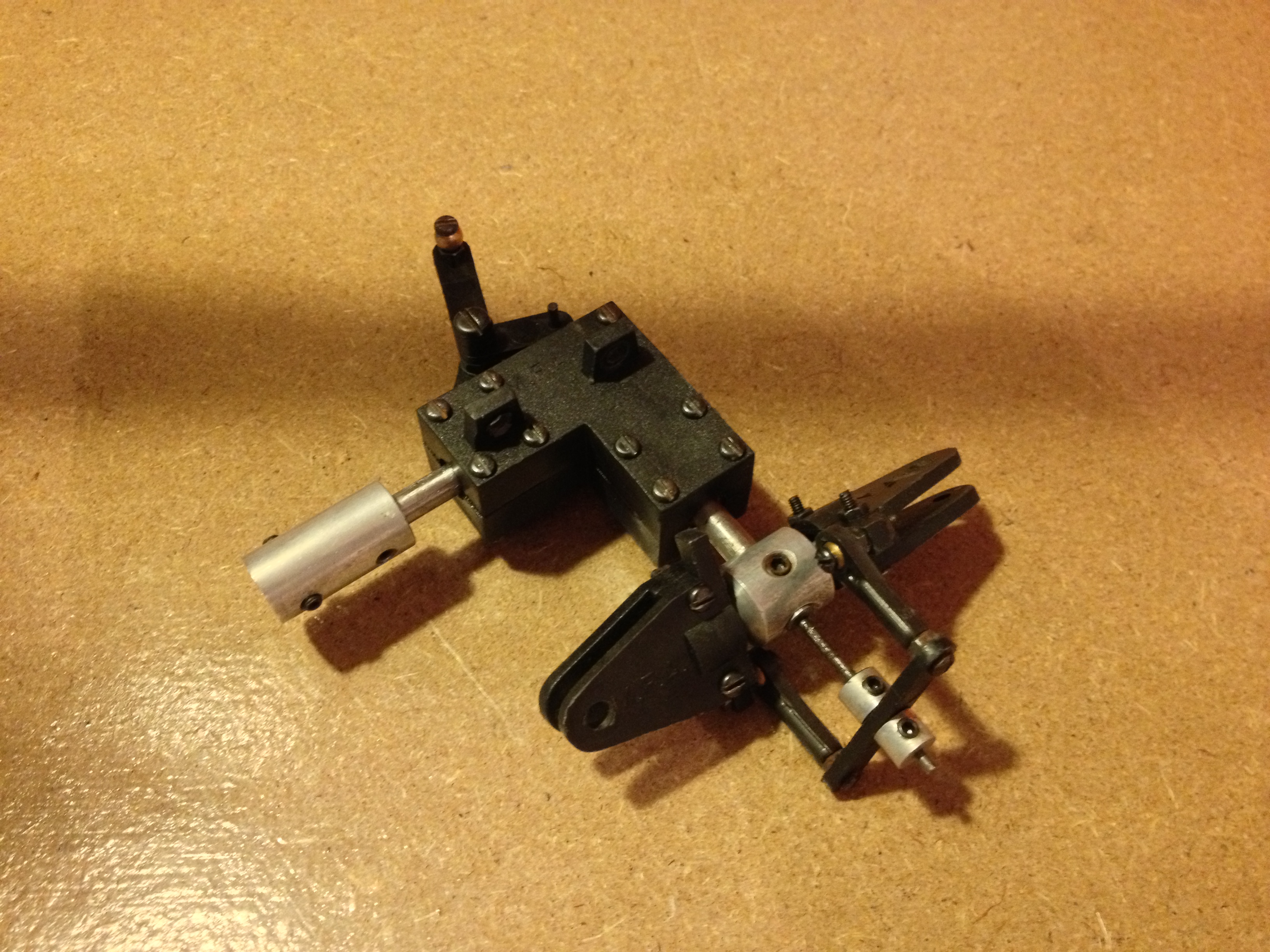
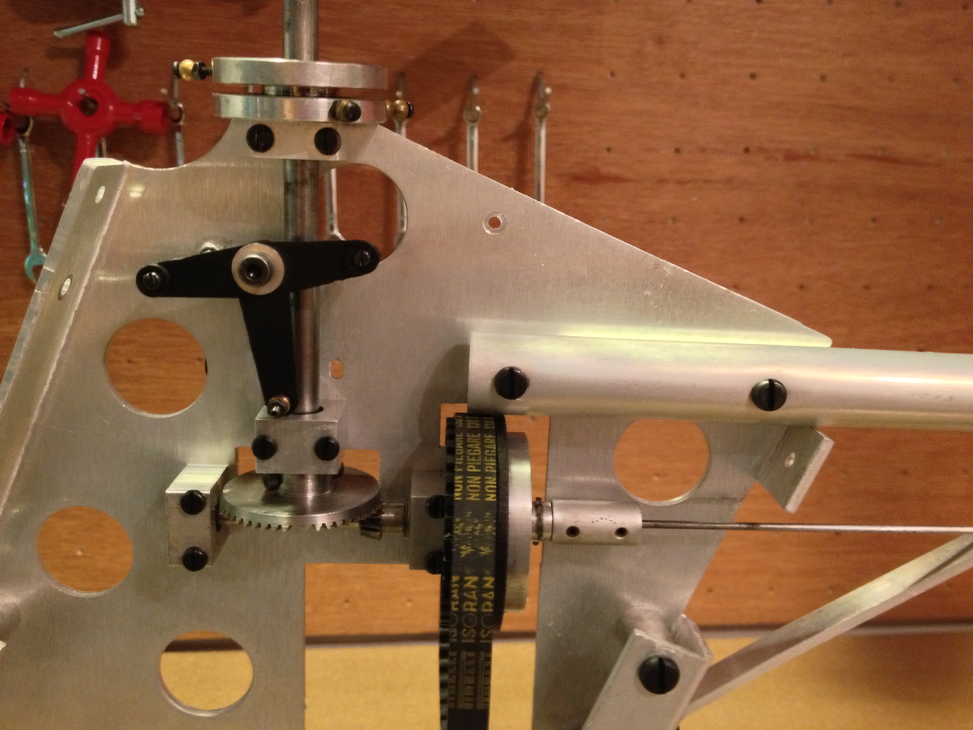
Main chassis assembled. Fitted is my favorite brand of engine for display models, a period correct, new in box, Series 1 SC40A.

IMG_0405

Woodwork cut out and protected with fuel proofer and sanded between coats until a thick glossy surface was achieved.

My MFA Sport 500 Collective

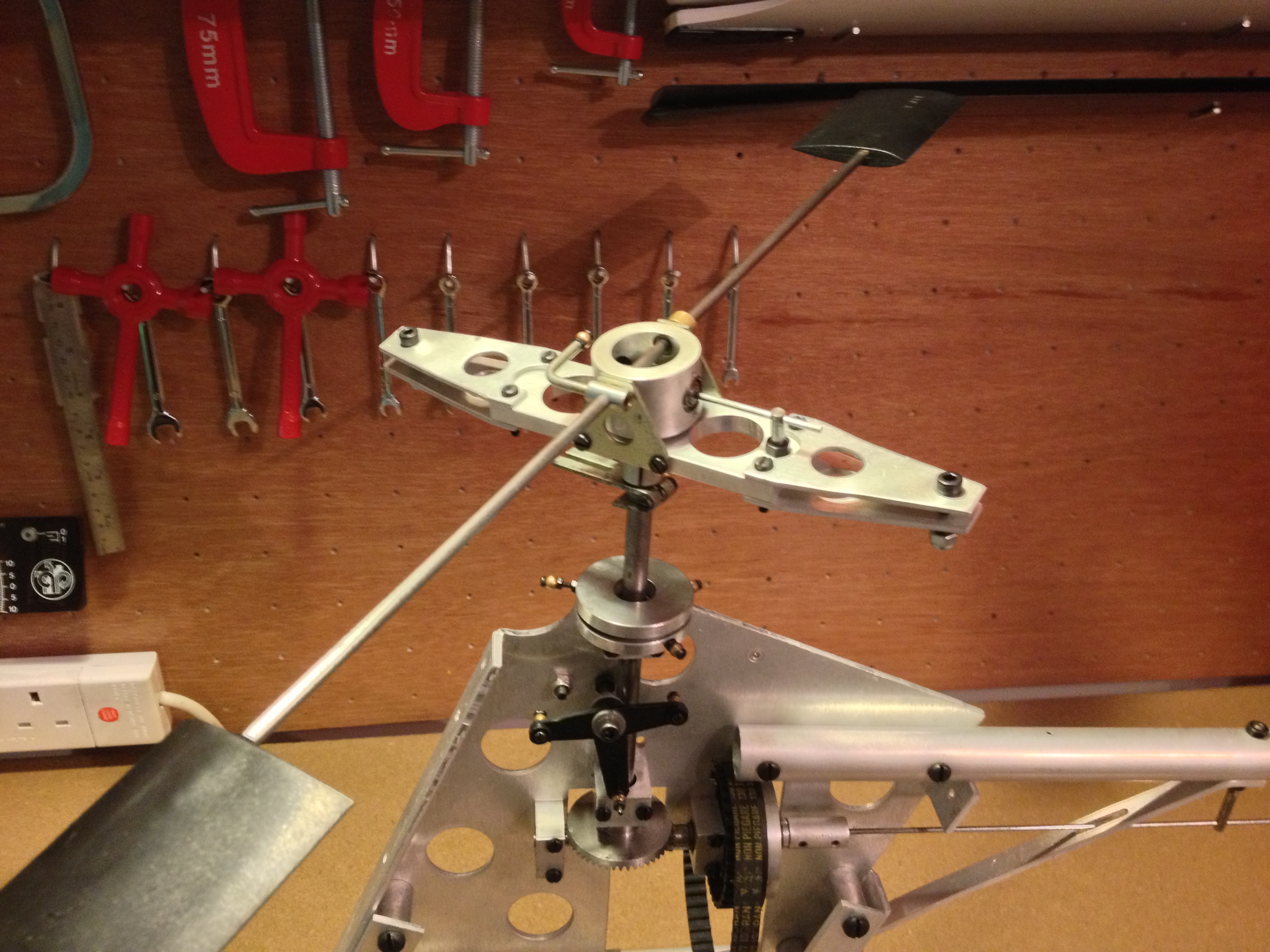
Radio tray complete with a vintage but fully functioning Quest gyro. (I’ve no idea how this will work in practice and might leave it in for ‘display’ and hide a miniature heading hold gyro behind it)

MFA Sport 500 Canopy Prep

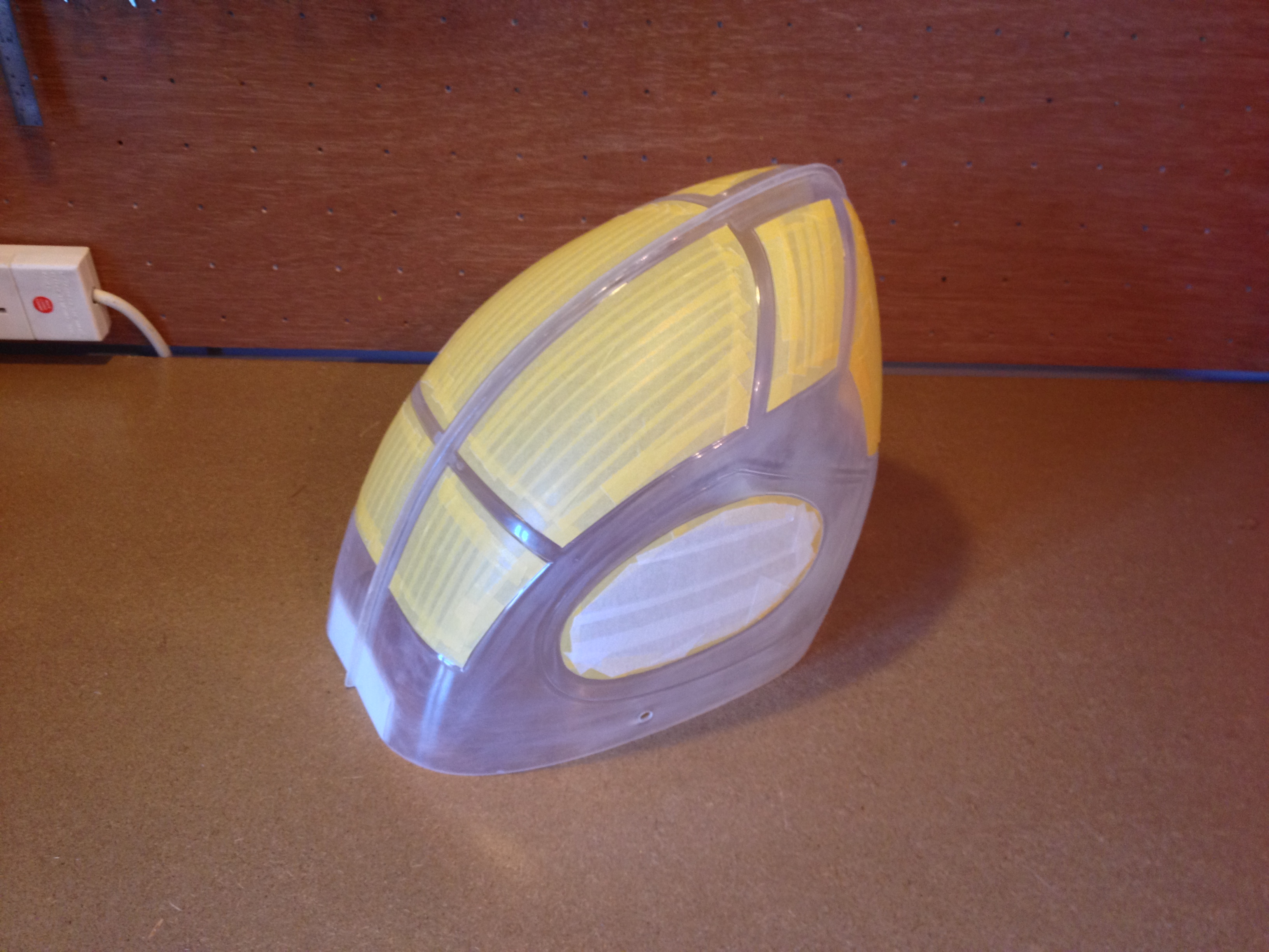
Canopy halves trimmed, joined and prepped for spraying

All painted with windows/doors outlined in trim tape.

Mechanics Left

Radio installation with receiver box and Quest gyro.

My MFA Sport 500 Collective (9)

Dummy 35 Mhz aerial is a must for a machine of this age!

Defining ‘As-New’

In one of my earlier posts I described why I purchased this particular Shuttle and why it means so much to me.  Well, getting the Shuttle fully restored has taken a while but here she is in all her glory.  Waiting for parts to come up on eBay has been the biggest hurdle.  I like my machines to look ‘as-new’ and it seems that ‘excellent condition’ is a matter of opinion when it comes to spare parts.  Still with a bit of patience I got all the parts I wanted.  The unused canopy and sticker set were the luckiest find and really finish the model off.

The now clean and refurbished OS 32SX-H was installed and a nice tidy (period correct for the Z-TS) CSM ICG360 gyro now resides on the mounting plate.  It’s currently got a MK1 rotor head but the rest is Shuttle Z-TS; albeit with an original Hirobo metal swashplate and now fully ball raced.  Personally I quite like the MK1 head with its metal grip plates and flybar arms plus it gives this model a bit of history allowing her to stand out from the rest.

Fully restored with replacement canopy and stickers.

IMG_0399

Cleaned OS 32-SXH and CSM ICG360 gyro installed. Good as new.

IMG_0398

To my mind there has never been a canopy system before of since like that on the Shuttle. With the sliding rail mechanism the canopy is ‘part’ of the machine as opposed to bolted over.